ESTA provides the critical link between the Victorian community and the state’s emergency services agencies. It provides Victoria’s 24-hour emergency call-taking and dispatch services for police, fire, ambulance and VICSES. In 2018-19, ESTA answered 2,605,574 calls for assistance, representing a call every 12 seconds or more than 7100 a day. The total number of events dispatched were 2,232,116 an average of more than 6100 each day.
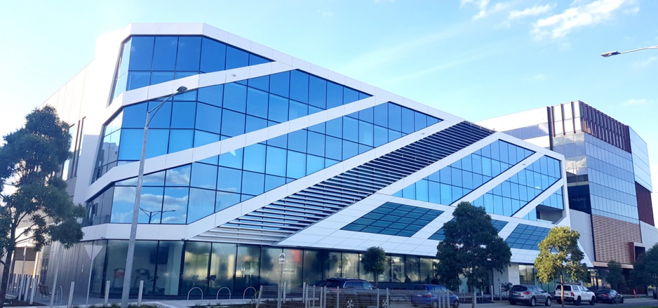
In 2018-19, ESTA implemented its Integrated Strategic Plan 2023 (ISP2023), a five-year road map to align its core services with the expectations of its partner agencies and the community. One of the core directives involved strengthening service resilience and surge management by moving to an “all services at multiple sites model.” Primarily, this involved a move of core facilities to a new site at Williams Landing.
As part of this move, ESTA – with the guidance of Lucid Consulting Australia – contracted the design and integration team at Vision One to develop and deploy audio visual turnkey solutions to support the needs of the new facility.
Vision One Technologies are proud to be associated with, and to deliver this major project with the collaborative assistance of Crestron ANZ and AT Control Pty Ltd.
Our scope of works involved the following:
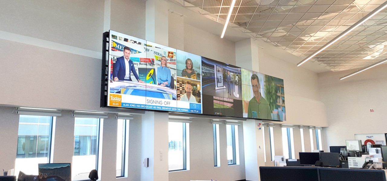
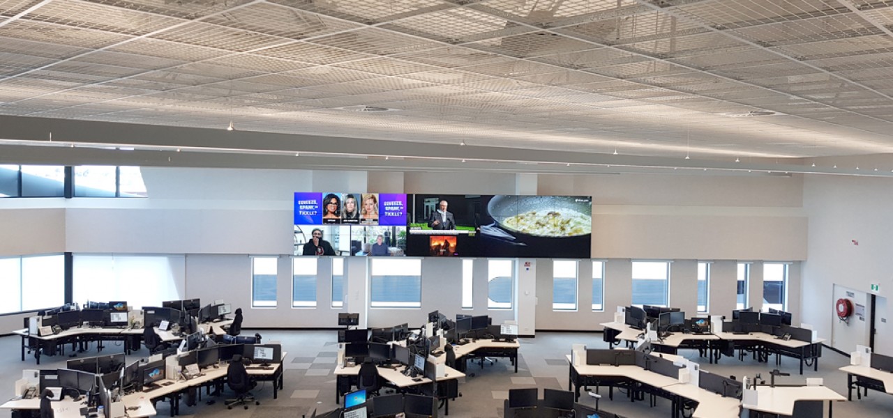
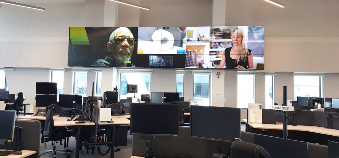
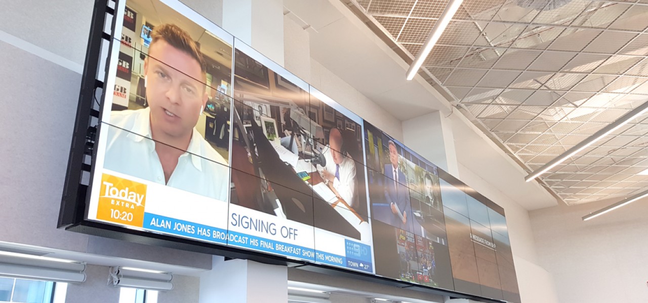
ESTA Operational Space – Video Wall and Control Room Vantage Points
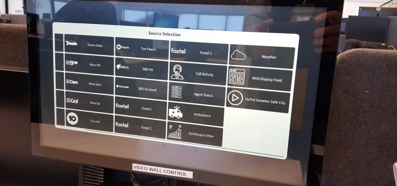
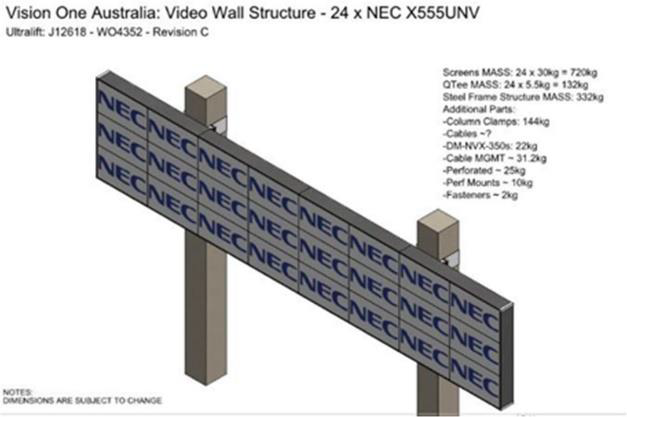
The operations floor will be provided with a video wall in addition to several other monitors mounted throughout areas as required. All monitors will be digitally addressable via IP controllers and video signal customizable over a network‐based application. The monitors are to show 1 of, or a mix of feeds that include but are not limited to Free‐to‐Air, Pay TV, safe city cameras, VICPOL air wing, CCTV, BOM weather feeds, call queues and other analytics from Genesys).
The video wall shall compose of a 3 row 8 column configuration as follows:
The video wall and 8 no. vantage point displays shall be able to view selected video from sources as located within the AV rack connected to the Crestron DM‐NVX system through ESTA’s network as well as laptop wired or wireless connections as located within the On‐Floor Manager’s table.
A set number of pre‐sets for configurations of the video wall will be required to be scoped out in conjunction with ESTA.
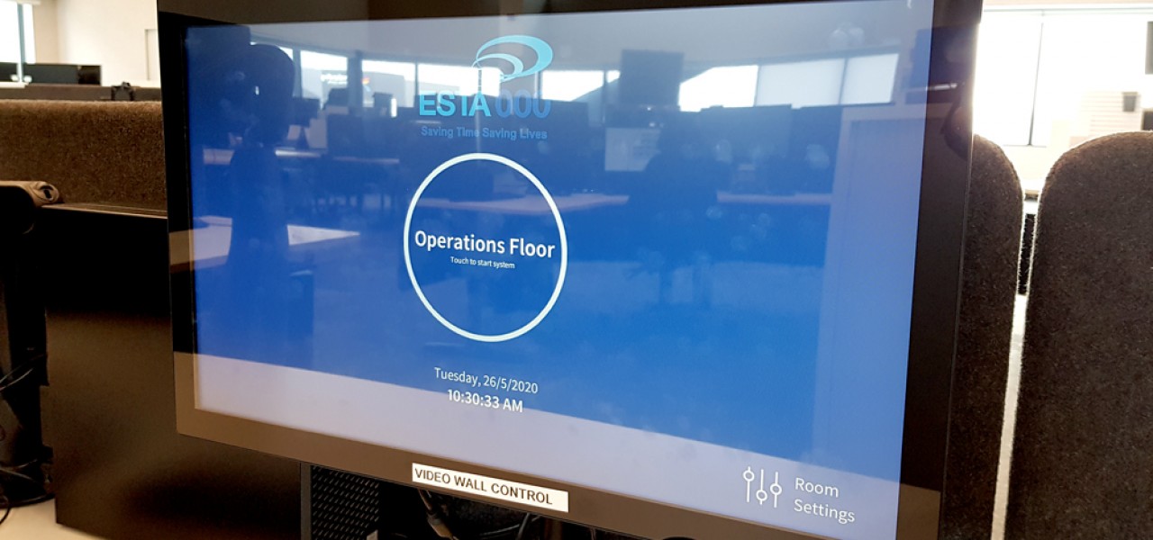
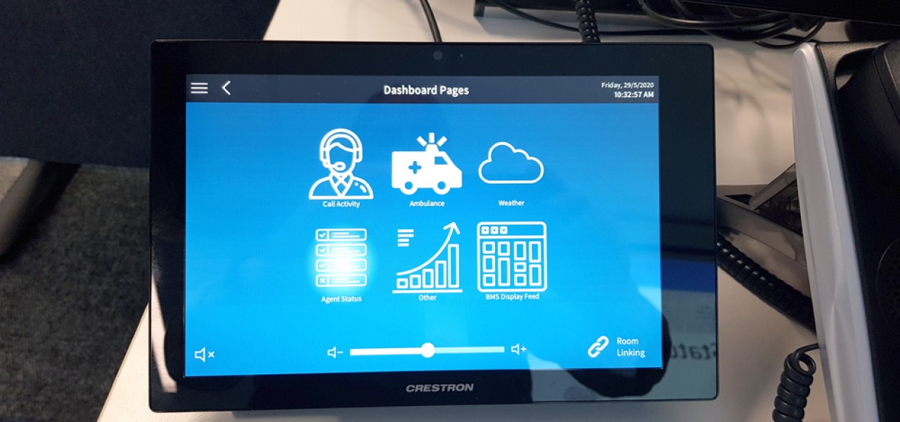
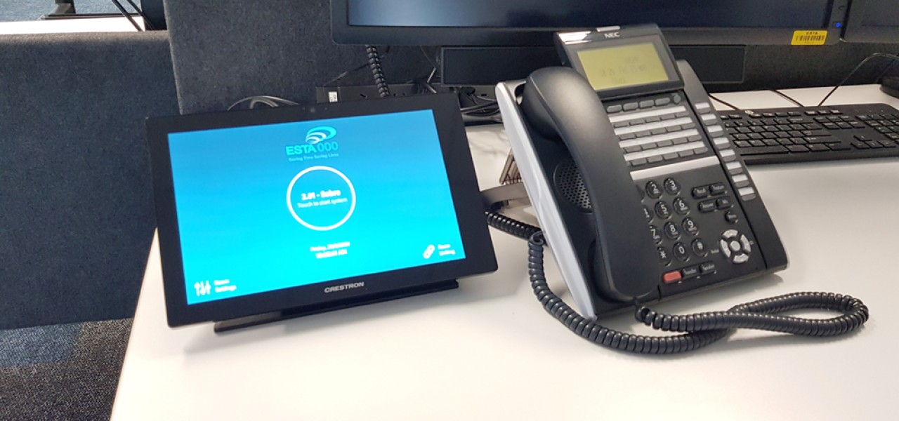
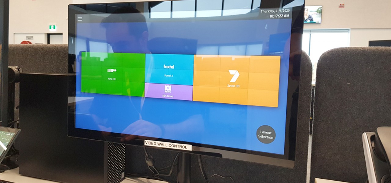
2 no. wired Crestron 21.5” touch screen powered by Crestron DGE-100 digital graphics engines will be mounted on the On‐Floor Manager’s table and will facilitate:
▪ Source selection and routing to vantage point displays and videowall.
▪ Videowall pre‐set, preview, control and selection; and
▪ Power control.
Note: NVX encoder/decoders at each desk location will allow managers to select and preview video wall content on Crestron 21” touch screens prior to sending content to video wall.
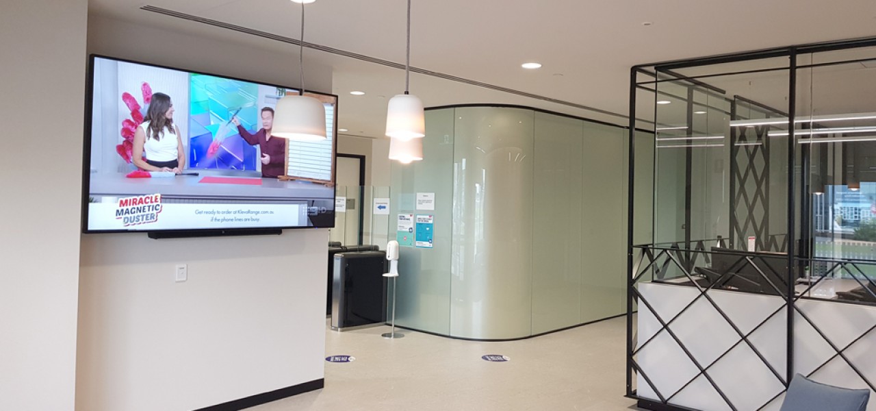
G.13 Lobby and G.12 Reception
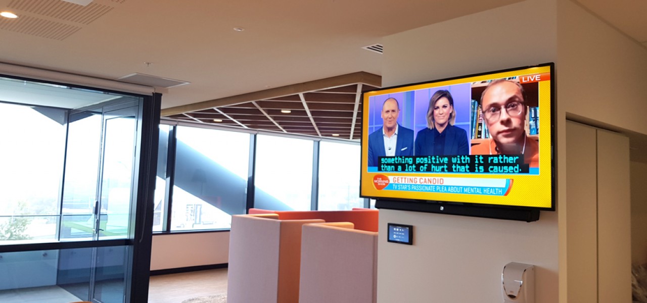
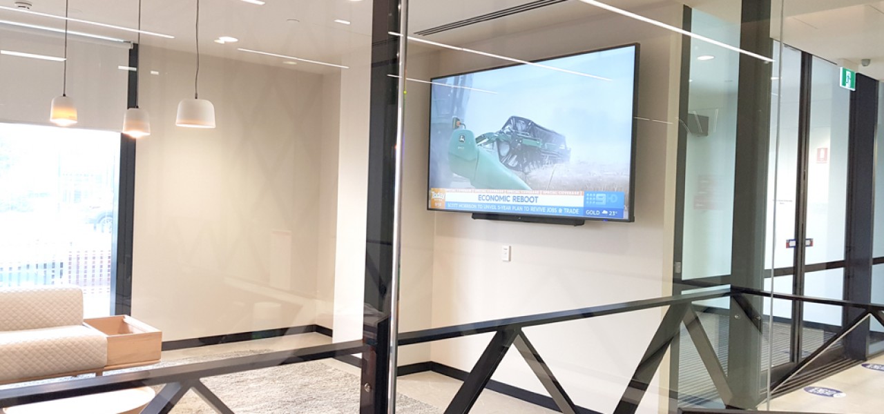
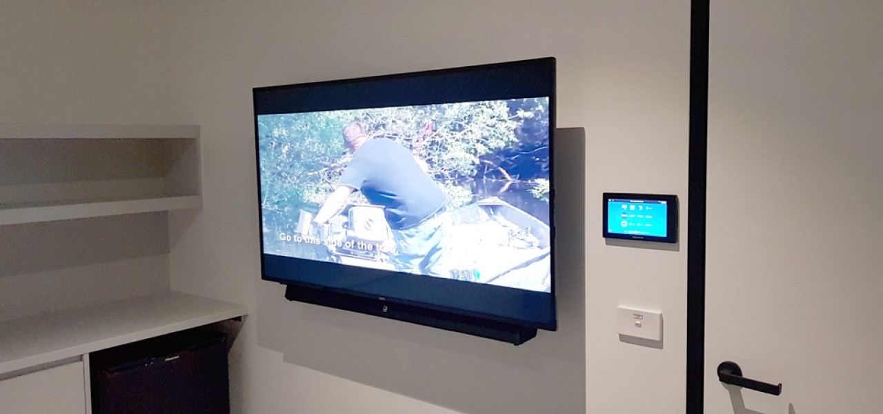
An 86” wall mounted display shall be able to view selected video and audio feeds sources as located within the AV rack connected to the Crestron DM‐NVX system through ESTA’s network.
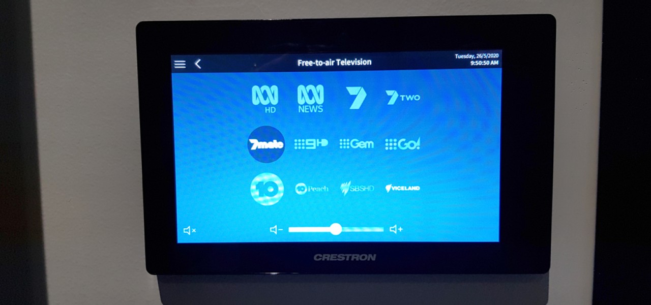
A wired Crestron TSW‐760 located within the reception counter will facilitate:
▪ Source selection and routing – sources to be confirmed by ESTA.
▪ Volume control; and
▪ Power control.
To use Bluetooth functionality of the provided soundbar, the user will have to use either the supplied soundbar remote control or side panel buttons of the soundbar.
A 32” wall mounted display will be mounted within the reception area for display of CCTV feeds. Control of display shall be via. manufacturer supplied remote control. CCTV source feeds shall be via. security contractor.
G.02 ‐ Gym
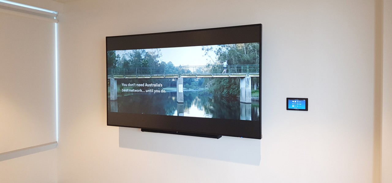
The 55” wall mounted display shall be able to view selected video and audio feeds sources as located within the AV rack connected to the Crestron DM‐NVX system through ESTA’s network
A wired Crestron TSW‐760 located wall mounted beside the display will facilitate:
▪ Source selection and routing – sources to be confirmed by ESTA.
▪ Volume control; and
▪ Power control.
To use Bluetooth functionality of the provided soundbar, the user will have to use either the supplied soundbar remote control or side panel buttons of the soundbar.
Training Room 1 L2.01, 2 L2.02 and 3 L2.03
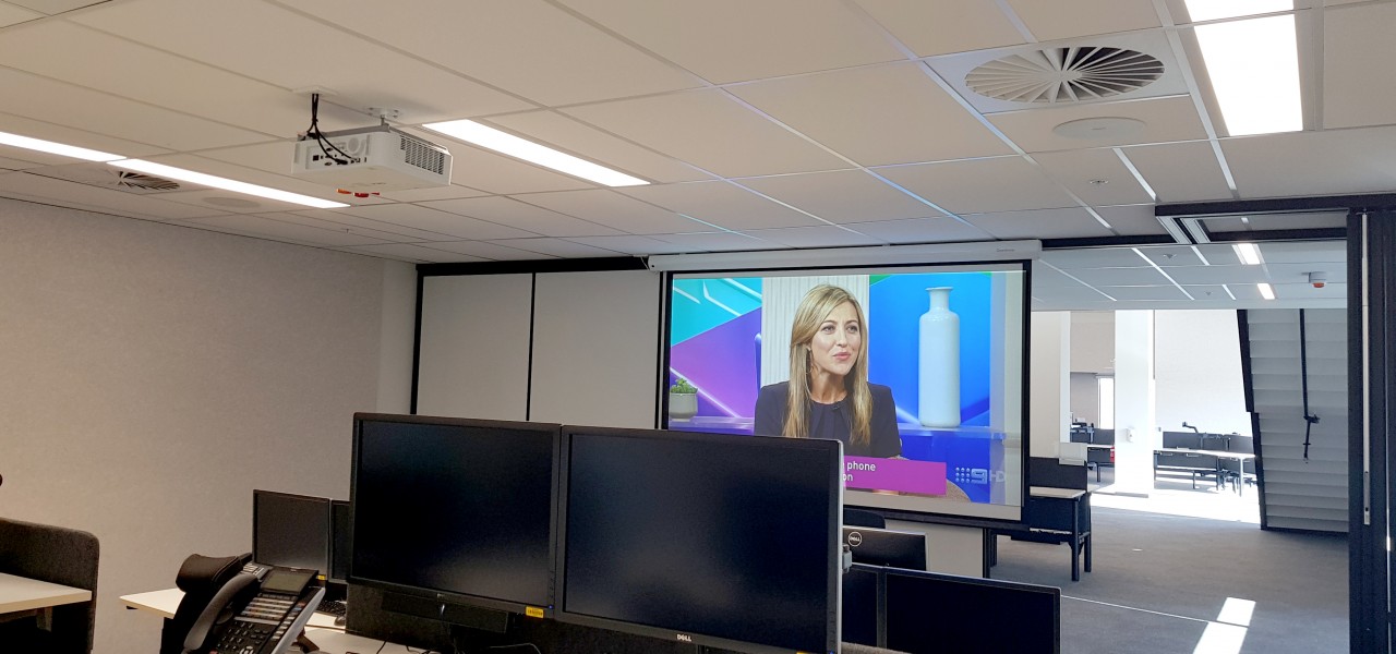
Training Rooms will be side by side with operable walls to allow training rooms to be sized to suit specific requirements. As such, interoperability of trainer workstations and projectors is required. It is a requirement by ESTA that workstation monitors are duplicated/mirrored to projector outputs and no display is lost at the workstation. The following is required to each training room: Functional Note: Allow for connection of each trainer workstation to each projector within the training area. Provide appropriate signal splitter and switch boxes as required.
The 3‐no. training room will be able to be used separately or joined as deemed necessary. To link the rooms, it is proposed that each room that will be link must be allowed from the rooms touch panel before the rooms link together.
Sources can be selected from local sources within the training rooms or sources located within the central AV rack for video and audio playback.
Each 10.1” Crestron Touch Panel will facilitate the following: ‐
▪ Source selection and routing – will include 3x PC sources including CAD (L), CAD (R), and Corporate laptop sources from each workstation location.
▪ Volume control.
▪ Power control; and
▪ Room linking.
Workstation monitors will be used to duplicate/mirror workstation video only. They are not to be used as screen preview for other sources.
Muster Room L2.13
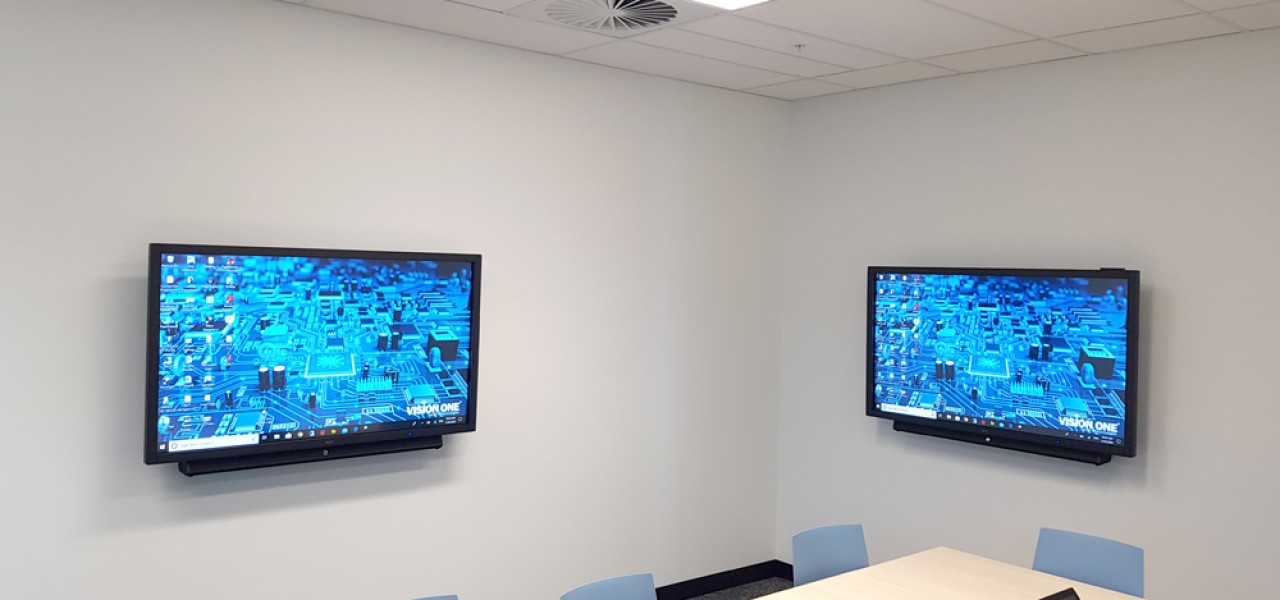
Fully interactive huddle space with multi‐touch monitors mounted to the wall. Screens to be fully integrated with ability to cast between screens and individual utilization of individual screens.
The muster room is intended for interactive collaboration use with users being able to drive source device connected via. USB to the host (PC or Laptop). Sources can be selected from local HDMI sources within the training room or sources located within the central AV rack for video and audio playback.
The 10.1” Crestron Touch Panel wall mounted will facilitate the following:
▪ Source selection and routing – including USB routing for interactivity.
▪ Volume control; and
▪ Power control.
A workstation connection for each interactive display have been allowed for and interactive displays will work independently of each other. Please note that audio reinforcement will playback audio from a Soundbar associated with each interactive display. However, audio will only be available from one display at any given time. A single wireless presenter and two hard‐wired laptop connections are provided at the tabletop in the centre of the table.
Meeting Room L3.07 and Meeting Room L3.08
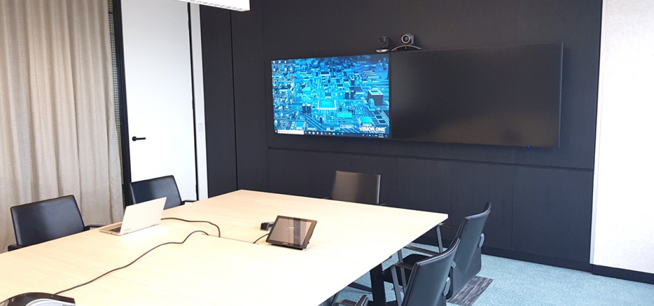
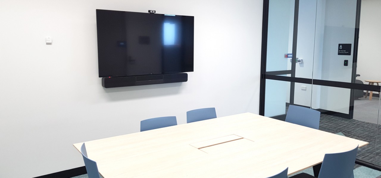
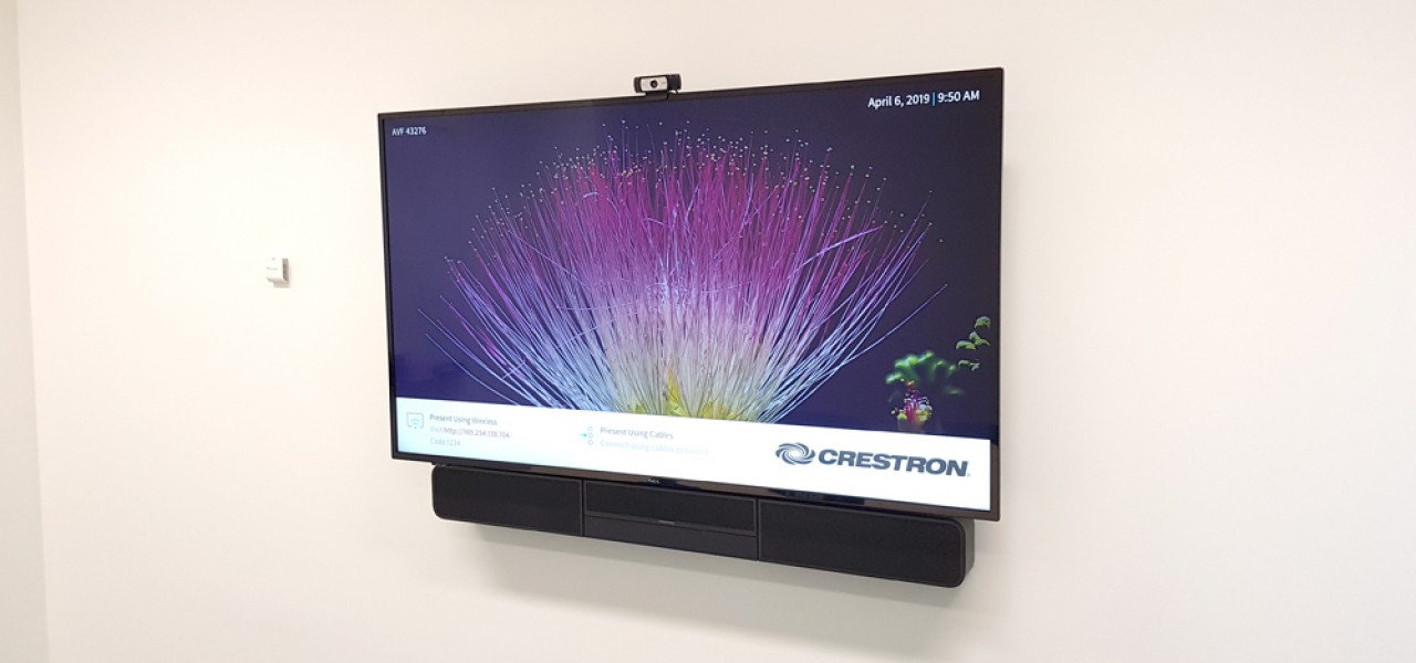
Connectivity to the TV will be via table mounted outlets. A Crestron Soundbar with camera and microphone will be provided for video calling; Audio will be provided from the Soundbar for pickup of speech/audio.
The meeting rooms are intended for daily presentation and soft codec video conferencing functions. Sources can be selected from local HDMI sources within the meeting room or sources located within the central AV rack for video and audio playback.
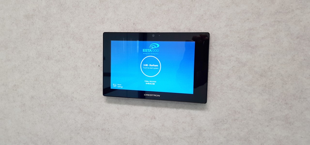
The 7” Crestron Touch Panel wall mounted will facilitate the following:
▪ Source selection and routing – including USB routing for interactivity; and
▪ Power control.
A single wireless presenter and or hard‐wired laptop connection is provided at the tabletop in the centre of the table.
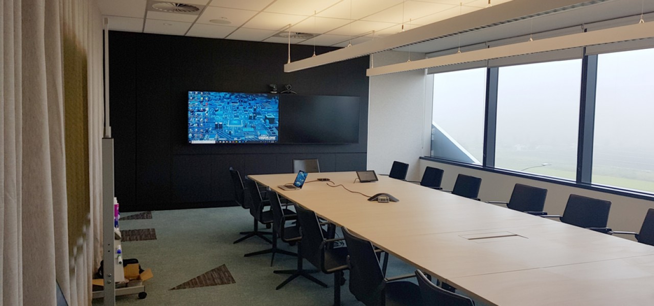
Conference Room L3.24
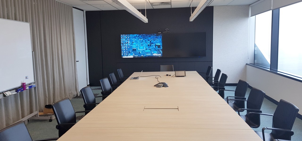
The conference room will be provided with full capability for video conferencing.
The conference rooms are intended for daily presentation and Polycom hard codec video conferencing functions – (Please note that Polycom conferencing will be used until such time as ESTA transition to Microsoft Teams Rooms for which the original scope was designed for – AT Controls to set up code for control of Polycom codec as per approved variations)
Sources can be selected from local sources within the meeting room or sources located within the central AV rack for video and audio playback.
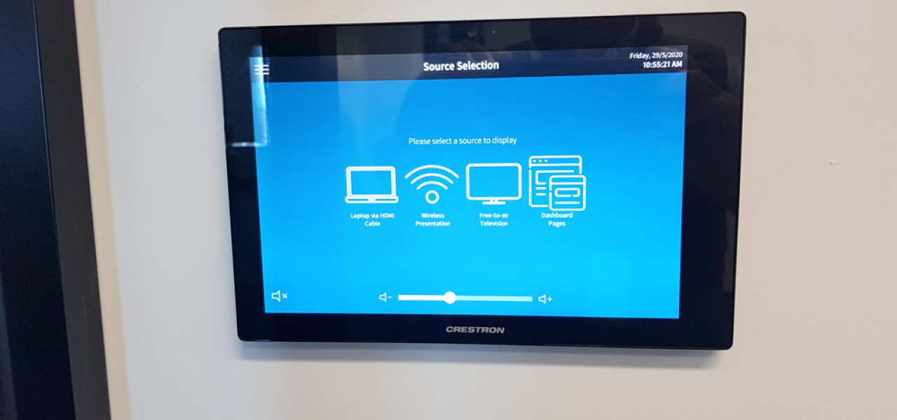
The 10” Crestron Touch Panel will facilitate the following:
▪ Source selection and routing – including USB routing for video conferencing.
▪ Power control.
The Polycom conference camera located at the front of the room will be provided for video capture of the participants of the video conferencing codec. Functionality will be provided as per according to the feature set of the Polycom HDX8000 VC codec.
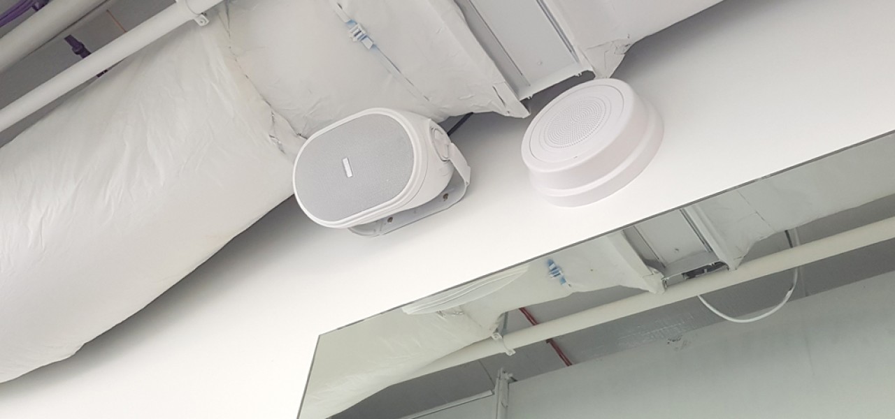
Audio reinforcement will be though provided in‐ceiling speakers.
2 no. wireless presenter and or hard‐wired laptop connection is provided at the tabletop at either end of the table.
All devices within the room will be able to utilize the room microphone, speakers, displays and web camera for hard codec conferencing.
Breakout Area L2.11
The 55” wall mounted display shall be able to view selected video and audio feeds sources as located within the AV rack connected to the Crestron DM‐NVX system through ESTA’s network
A wired Crestron TSW‐760 located wall mounted beside the display will facilitate:
▪ Source selection and routing – sources to be confirmed by ESTA.
▪ Volume control; and
▪ Power control.
To use Bluetooth functionality of the provided soundbar, the user will have to use either the supplied soundbar remote control or side panel buttons of the soundbar.
ESO Breakout Area L3.12
The 55” wall mounted display shall be able to view selected video and audio feeds sources as located within the AV rack connected to the Crestron DM‐NVX system through ESTA’s network
A wired Crestron TSW‐760 located wall mounted beside the display will facilitate:
▪ Source selection and routing – sources to be confirmed by ESTA.
▪ Volume control; and
▪ Power control.
To use Bluetooth functionality of the provided soundbar, the user will have to use either the supplied soundbar remote control or side panel buttons of the soundbar.
Theatre L3.04
The 86” wall mounted display shall be able to view selected video and audio feeds sources as located within the AV rack connected to the Crestron DM‐NVX system through ESTA’s network.
A wired Crestron TSW‐760 located within the reception counter will facilitate:
▪ Source selection and routing – sources to be confirmed by ESTA.
▪ Volume control; and
▪ Power control.
To use Bluetooth functionality of the provided soundbar, the user will have to use either the supplied soundbar remote control or side panel buttons of the soundbar.
Central AV Equipment (L3.19 ICT/LAN)
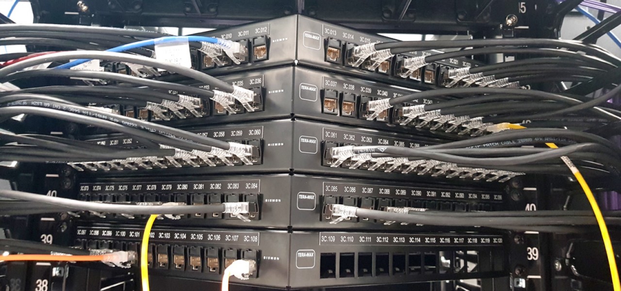
1. IP distribution of media (IPTV) is noted to be through Crestron DM‐NVX system and will be used interchangeably.
2. MATV infrastructure will be installed by based build
3. Set Top Box inclusive Foxtel and Free‐to‐air, CCTV decoders, Air Wing and Safe City decoders/sources will be provided by client.
4. All PCs or interfaces from BoM weather feeds, analytics PC will be by client
5. All sources within the central AV equipment location connected to the DM‐NVX system will be able to routed to any room/system which contains a DM‐NVX IPTV decoder.
6. It is suggested each DM‐NVX encoder is connected to a specific channel for ease of use for the end‐user, except for:
▪ Waiting and Reception Display.
▪ ESO Breakout Area Display.
▪ Gym Display; and
▪ Theatre Display.
7. (Point 6) is suggested because users may want to access entertainment channels and various other channels not required by other rooms.


